 0 items
Map Material Loss, Compare Against Nominal Thickness, and Document Large Inspection Areas
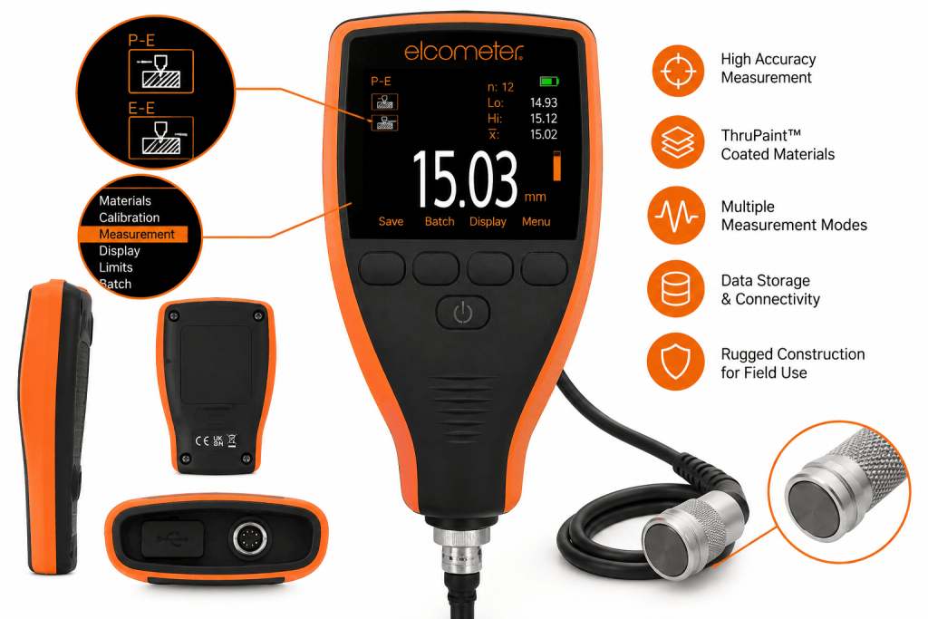
Store 100,000 readings in up to 1,000 sequential or grid batches. Factory calibrated to 39 different materials. MTG2, MTG4, MTG6, the MTG8 up to three calibrations in memory, ideal for users who are measuring a variety of materials or thicknesses. Using the alpha-numeric function, calibration memories can be re-named to suit the calibration setting. The Elcometer MTG8 Ultrasonic Material Thickness Gauge combines high-accuracy ultrasonic thickness measurement with advanced corrosion-mapping, data-logging, and analysis tools. It measures material thickness when only one side of a component is accessible, making it particularly useful for inspecting pipelines, tanks, pressure vessels, structural components, and industrial equipment for corrosion, erosion, or other material loss.
Beyond individual thickness readings, the MTG8 can organize measurements into grid batches, display B-Scan cross-sectional profiles, identify minimum thickness during scanning, and compare readings against a user-defined nominal thickness. Echo-Echo ThruPaint™ also allows the underlying material to be measured through compatible coatings without including the coating thickness in the result.
Map Corrosion with Grid Batching
The MTG8 can store measurements in grid-type batches that correspond to defined inspection locations on a component. Readings are arranged in a spreadsheet-style format, providing a systematic way to inspect large surfaces and identify localized wall loss. An obstruction function allows inaccessible grid positions to be recorded without disrupting the inspection sequence.
Visualize Material Loss with B-Scan
B-Scan provides a time-based, two-dimensional cross-sectional representation of the material beneath the transducer. As the probe moves across the surface, changes in measured thickness become visible on the display, helping inspectors identify areas where corrosion, erosion, or other material loss has changed the back-wall profile.
Find the Thinnest Area with Scan Mode
When inspecting a larger area, Scan Mode allows the transducer to be moved continuously across the surface rather than taking isolated measurements. The MTG8 can capture readings at selectable rates of 4, 8, or 16Hz and display key values such as the minimum thickness found during the scan, making it easier to locate localized thinning.
MTG 8 MODEL SPECIFICATIONS
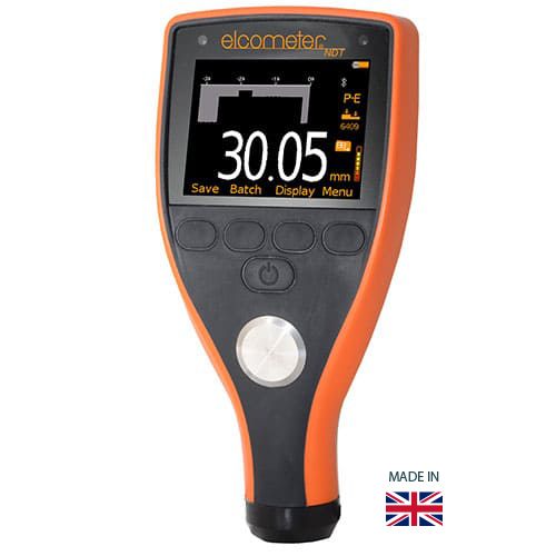
MTG8DL (Includes data logging) add to cart
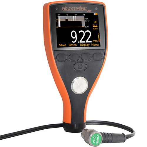
MTG8DL-TXC (Includes data logging) add to cart
Gauge, complete with 5MHz ¼” right angle dual element transducer
SELECT YOUR MODEL ON TOP OF THE PAGE TO VIEW THE PRICE
How to do a Grid corrosion inspection using the Elcometer MTG8
The MTG8 has audible warnings for user-definable upper and lower limits. Such limits can be set or for each batch.
In the differential mode, once a user-defined thickness value is set, the gauge displays the measured thickness with the variation from the nominal value.
The MTG8 offers B-Scan, a time-based, cross-sectional 2-dimensional graphical view of the material under test, ideal for relative depth analysis. The zoom of the B-Scan reading can either be set to automatic or can be defined by the user to focus on areas of interest.
The MTG8 stores 100,000 readings in up to 1,000 sequential or grid-type batches. While grid batching, readings are stored in a spreadsheet-type format. The Obst feature, allows the user to record an obstruction within the grid.
Compatible with ElcoMaster™, PC & Mobile Apps, readings can be downloaded via USB or Bluetooth® to PC, iOS, or Android™ devices for further analysis and reporting.
Pulsed – Echo Mode (P-E):
Ideal for pit and flaw detection, the total thickness from the base of the transducer to the material density boundary (typically the back wall) is measured.
Echo – Echo ThruPaint™ Mode (E-E):
Also known as ThruPaint™ mode, the coating thickness is ignored and the material thickness from the top surface of the material to the material density boundary (typically the back-wall) is measured. To use Echo-Echo ThruPaint™ mode, a high-damped, coating thickness transducer is required.
Velocity Mode (VM):
Velocity mode measures the speed of sound of materials and is ideal for determining the homogeneity of a material/alloy and the correct velocity of material for calibration.
Compare Every Reading Against Nominal Thickness
Differential Mode compares the measured thickness with a user-defined nominal or target value. Instead of requiring the inspector to calculate the difference manually, the gauge immediately displays how much thicker or thinner the measured area is than the specified reference thickness.
Measure Through Paint with Echo-Echo ThruPaint™
Echo-Echo ThruPaint™ mode measures the thickness of the underlying material while excluding the coating from the result. This allows inspectors to assess coated components without removing otherwise sound paint solely to obtain a wall-thickness measurement. A compatible high-damped coating-thickness transducer is required for this mode.
High and Low Limits for Immediate Pass/Fail Feedback
User-defined upper and lower thickness limits can be assigned to readings or individual batches. When a measurement falls outside the acceptable range, the MTG8 provides audible and visual warnings, allowing problem areas to be recognized immediately during inspection.
Store Up to 100,000 Measurements
The MTG8 stores up to 100,000 readings in as many as 1,000 sequential or grid batches. This capacity makes it well suited to inspection programs involving many measurement locations, repeated surveys, or large assets where traceable measurement records are required.
Save Calibration Setups for Repeated Inspection Work
Up to three calibration settings can be stored in memory and given alphanumeric names. Inspectors working with different materials, transducers, or thickness ranges can therefore recall an appropriate calibration instead of repeating the complete calibration procedure each time the inspection changes.
Measure a Wide Range of Materials
The MTG8 includes 39 factory-programmed material velocities and a Velocity Mode covering 1,250–10,000m/s (0.0492–0.3937in/µs). Together with its calibration functions and range of compatible transducers, this allows thickness measurements on many materials beyond conventional carbon steel.
Measure from 0.63 to 500mm in Pulse-Echo Mode
Depending on the material and transducer, Pulse-Echo mode provides a nominal measurement range of 0.63–500mm (0.025–19.999in). Accuracy is ±0.05mm between 0.63 and 9.99mm and ±0.5% between 10 and 500mm.
Transfer Inspection Data by USB or Bluetooth®
Stored measurements can be transferred to ElcoMaster® through USB or Bluetooth® for analysis and reporting on compatible computers and mobile devices. This allows thickness readings, inspection grids, and associated project information to become part of a traceable digital inspection record.
Frequently Asked Questions
When is B-Scan more useful than simply recording thickness readings?
B-Scan is particularly valuable when the inspector needs to understand how thickness changes while moving across a component. Instead of reviewing a series of isolated numbers, the inspector sees a cross-sectional representation of the measured back-wall profile, making significant changes in material thickness easier to recognize.
What is the difference between Scan Mode and B-Scan?
Scan Mode is useful for rapidly collecting measurements across an area and identifying values such as the minimum thickness encountered. B-Scan uses measurements collected as the probe moves to create a graphical cross-sectional representation of thickness changes. Scan Mode emphasizes rapid numerical assessment, while B-Scan adds visual interpretation of the thickness profile.
Why is minimum thickness often more important than average thickness in corrosion inspection?
Localized corrosion or pitting can leave a small area substantially thinner than the surrounding material. An acceptable average can therefore conceal a potentially critical thin spot. Scan and grid inspections help locate these minimum values so they can be evaluated against the asset’s allowable remaining wall thickness.
When should I use a grid batch instead of a sequential batch?
A sequential batch is appropriate when readings simply need to be recorded in the order they are taken. Grid batching is preferable when each measurement must correspond to a defined physical location on a tank, pipe, vessel, or other surface. This makes it easier to map wall thickness and return to areas of concern during future inspections.
How does Differential Mode help when inspecting an asset with a known original wall thickness?
The original or nominal wall thickness can be entered as the reference value. Differential Mode then shows the measured thickness together with its variation from that target, allowing the inspector to recognize material loss immediately without calculating the difference for every reading.
Can the MTG8 measure corrosion beneath paint without removing the coating?
Yes, when Echo-Echo ThruPaint™ mode is used with a compatible high-damped transducer. This mode excludes the coating from the displayed substrate thickness, allowing remaining wall thickness to be assessed without removing intact paint merely to make the measurement.
Why would I save multiple calibration memories?
Ultrasonic measurements depend on material velocity, transducer selection, and the inspection setup. If an inspector regularly switches between different materials or thickness ranges, stored calibration memories allow previously established configurations to be recalled quickly and reduce repetitive setup work.
How does the MTG8 improve repeat inspections of the same tank or structure?
Grid-based measurement locations and stored inspection data make it easier to perform subsequent measurements systematically at corresponding areas. Comparing measurements from repeated inspections can help establish whether wall loss is progressing and identify locations that require closer monitoring.
When should I choose the MTG8 instead of the MTG4?
The MTG4 is well suited to general ultrasonic thickness measurements, including measurements through coatings. The MTG8 is the stronger choice for larger or more demanding inspection programs because it adds extensive data logging, sequential and grid batching, Scan Mode, B-Scan, Differential Mode, user-defined limits, and multiple calibration memories.
View more technical specifications
With Data Logging
With Transducer and Data Logging
Map Material Loss, Compare Against Nominal Thickness, and Document Large Inspection Areas
Store 100,000 readings in up to 1,000 sequential or grid batches. Factory calibrated to 39 different materials. MTG2, MTG4, MTG6, the MTG8 up to three calibrations in memory, ideal for users who are measuring a variety of materials or thicknesses. Using the alpha-numeric function, calibration memories can be re-named to suit the calibration setting. The Elcometer MTG8 Ultrasonic Material Thickness Gauge combines high-accuracy ultrasonic thickness measurement with advanced corrosion-mapping, data-logging, and analysis tools. It measures material thickness when only one side of a component is accessible, making it particularly useful for inspecting pipelines, tanks, pressure vessels, structural components, and industrial equipment for corrosion, erosion, or other material loss.
Beyond individual thickness readings, the MTG8 can organize measurements into grid batches, display B-Scan cross-sectional profiles, identify minimum thickness during scanning, and compare readings against a user-defined nominal thickness. Echo-Echo ThruPaint™ also allows the underlying material to be measured through compatible coatings without including the coating thickness in the result.
Map Corrosion with Grid Batching
The MTG8 can store measurements in grid-type batches that correspond to defined inspection locations on a component. Readings are arranged in a spreadsheet-style format, providing a systematic way to inspect large surfaces and identify localized wall loss. An obstruction function allows inaccessible grid positions to be recorded without disrupting the inspection sequence.
Visualize Material Loss with B-Scan
B-Scan provides a time-based, two-dimensional cross-sectional representation of the material beneath the transducer. As the probe moves across the surface, changes in measured thickness become visible on the display, helping inspectors identify areas where corrosion, erosion, or other material loss has changed the back-wall profile.
Find the Thinnest Area with Scan Mode
When inspecting a larger area, Scan Mode allows the transducer to be moved continuously across the surface rather than taking isolated measurements. The MTG8 can capture readings at selectable rates of 4, 8, or 16Hz and display key values such as the minimum thickness found during the scan, making it easier to locate localized thinning.
MTG 8 MODEL SPECIFICATIONS
MTG8DL (Includes data logging) add to cart
MTG8DL-TXC (Includes data logging) add to cart
Gauge, complete with 5MHz ¼” right angle dual element transducer
SELECT YOUR MODEL ON TOP OF THE PAGE TO VIEW THE PRICE
How to do a Grid corrosion inspection using the Elcometer MTG8
The MTG8 has audible warnings for user-definable upper and lower limits. Such limits can be set or for each batch.
In the differential mode, once a user-defined thickness value is set, the gauge displays the measured thickness with the variation from the nominal value.
The MTG8 offers B-Scan, a time-based, cross-sectional 2-dimensional graphical view of the material under test, ideal for relative depth analysis. The zoom of the B-Scan reading can either be set to automatic or can be defined by the user to focus on areas of interest.
The MTG8 stores 100,000 readings in up to 1,000 sequential or grid-type batches. While grid batching, readings are stored in a spreadsheet-type format. The Obst feature, allows the user to record an obstruction within the grid.
Compatible with ElcoMaster™, PC & Mobile Apps, readings can be downloaded via USB or Bluetooth® to PC, iOS, or Android™ devices for further analysis and reporting.
Pulsed – Echo Mode (P-E):
Ideal for pit and flaw detection, the total thickness from the base of the transducer to the material density boundary (typically the back wall) is measured.
Echo – Echo ThruPaint™ Mode (E-E):
Also known as ThruPaint™ mode, the coating thickness is ignored and the material thickness from the top surface of the material to the material density boundary (typically the back-wall) is measured. To use Echo-Echo ThruPaint™ mode, a high-damped, coating thickness transducer is required.
Velocity Mode (VM):
Velocity mode measures the speed of sound of materials and is ideal for determining the homogeneity of a material/alloy and the correct velocity of material for calibration.
Compare Every Reading Against Nominal Thickness
Differential Mode compares the measured thickness with a user-defined nominal or target value. Instead of requiring the inspector to calculate the difference manually, the gauge immediately displays how much thicker or thinner the measured area is than the specified reference thickness.
Measure Through Paint with Echo-Echo ThruPaint™
Echo-Echo ThruPaint™ mode measures the thickness of the underlying material while excluding the coating from the result. This allows inspectors to assess coated components without removing otherwise sound paint solely to obtain a wall-thickness measurement. A compatible high-damped coating-thickness transducer is required for this mode.
High and Low Limits for Immediate Pass/Fail Feedback
User-defined upper and lower thickness limits can be assigned to readings or individual batches. When a measurement falls outside the acceptable range, the MTG8 provides audible and visual warnings, allowing problem areas to be recognized immediately during inspection.
Store Up to 100,000 Measurements
The MTG8 stores up to 100,000 readings in as many as 1,000 sequential or grid batches. This capacity makes it well suited to inspection programs involving many measurement locations, repeated surveys, or large assets where traceable measurement records are required.
Save Calibration Setups for Repeated Inspection Work
Up to three calibration settings can be stored in memory and given alphanumeric names. Inspectors working with different materials, transducers, or thickness ranges can therefore recall an appropriate calibration instead of repeating the complete calibration procedure each time the inspection changes.
Measure a Wide Range of Materials
The MTG8 includes 39 factory-programmed material velocities and a Velocity Mode covering 1,250–10,000m/s (0.0492–0.3937in/µs). Together with its calibration functions and range of compatible transducers, this allows thickness measurements on many materials beyond conventional carbon steel.
Measure from 0.63 to 500mm in Pulse-Echo Mode
Depending on the material and transducer, Pulse-Echo mode provides a nominal measurement range of 0.63–500mm (0.025–19.999in). Accuracy is ±0.05mm between 0.63 and 9.99mm and ±0.5% between 10 and 500mm.
Transfer Inspection Data by USB or Bluetooth®
Stored measurements can be transferred to ElcoMaster® through USB or Bluetooth® for analysis and reporting on compatible computers and mobile devices. This allows thickness readings, inspection grids, and associated project information to become part of a traceable digital inspection record.
Frequently Asked Questions
When is B-Scan more useful than simply recording thickness readings?
B-Scan is particularly valuable when the inspector needs to understand how thickness changes while moving across a component. Instead of reviewing a series of isolated numbers, the inspector sees a cross-sectional representation of the measured back-wall profile, making significant changes in material thickness easier to recognize.
What is the difference between Scan Mode and B-Scan?
Scan Mode is useful for rapidly collecting measurements across an area and identifying values such as the minimum thickness encountered. B-Scan uses measurements collected as the probe moves to create a graphical cross-sectional representation of thickness changes. Scan Mode emphasizes rapid numerical assessment, while B-Scan adds visual interpretation of the thickness profile.
Why is minimum thickness often more important than average thickness in corrosion inspection?
Localized corrosion or pitting can leave a small area substantially thinner than the surrounding material. An acceptable average can therefore conceal a potentially critical thin spot. Scan and grid inspections help locate these minimum values so they can be evaluated against the asset’s allowable remaining wall thickness.
When should I use a grid batch instead of a sequential batch?
A sequential batch is appropriate when readings simply need to be recorded in the order they are taken. Grid batching is preferable when each measurement must correspond to a defined physical location on a tank, pipe, vessel, or other surface. This makes it easier to map wall thickness and return to areas of concern during future inspections.
How does Differential Mode help when inspecting an asset with a known original wall thickness?
The original or nominal wall thickness can be entered as the reference value. Differential Mode then shows the measured thickness together with its variation from that target, allowing the inspector to recognize material loss immediately without calculating the difference for every reading.
Can the MTG8 measure corrosion beneath paint without removing the coating?
Yes, when Echo-Echo ThruPaint™ mode is used with a compatible high-damped transducer. This mode excludes the coating from the displayed substrate thickness, allowing remaining wall thickness to be assessed without removing intact paint merely to make the measurement.
Why would I save multiple calibration memories?
Ultrasonic measurements depend on material velocity, transducer selection, and the inspection setup. If an inspector regularly switches between different materials or thickness ranges, stored calibration memories allow previously established configurations to be recalled quickly and reduce repetitive setup work.
How does the MTG8 improve repeat inspections of the same tank or structure?
Grid-based measurement locations and stored inspection data make it easier to perform subsequent measurements systematically at corresponding areas. Comparing measurements from repeated inspections can help establish whether wall loss is progressing and identify locations that require closer monitoring.
When should I choose the MTG8 instead of the MTG4?
The MTG4 is well suited to general ultrasonic thickness measurements, including measurements through coatings. The MTG8 is the stronger choice for larger or more demanding inspection programs because it adds extensive data logging, sequential and grid batching, Scan Mode, B-Scan, Differential Mode, user-defined limits, and multiple calibration memories.
View more technical specifications
With Data Logging
With Transducer and Data Logging