Reasons for surface corrosion, faulty coating and cracks.
Quality control of any industrial coating should include the following concerns:
- Runny and soggy coating: uneven thickness due to gravity pulling paint down
- Cissing: air bubbles on the coating
- Cratering: gaps in coating due to sub-coating failure (humidity)
- Pinholes: Caused by air or dust particles
- Over Coating: paint cracking during /after curing
- Under Coating: Lack of coating in pointy or uneven areas
Testing method 1. The Low Voltage Pinhole method / Wet Sponge technique (Try Elcometer 270)
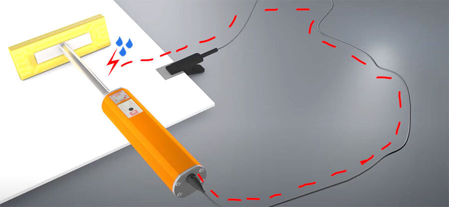
Ideal for powder coatings, or any coatings less than 500μm (20mils) thick, as you do not wish to damage the coating. This method only detects pinholes. Pinholes are important to detect as they allow moisture to access the steel. When you pass a damp sponge over holes in the coating, the water from the sponge triggers a low voltage circuit over each hole. The unit alarms, letting you know its location. Read here in greater detail
Testing method 2. The High Voltage or Holiday Detection method
In this case, the voltage should be high enough to break through the coating that is too thin (even if there are no holes) and give a signal.
Setting correct voltage is vital
Testing with too low a voltage could fail to bridge the gap between the probe and substrate, failing to signal flaws. Conversely, if the voltage is too high, it could damage the coating, reporting false flaws and even creating them in the process.
Testing with bright blue sparks is a clear sign the voltage is too high, and is probably damaging the coating. Bright blue sparks are a clear sign that voltage is too high.
The voltage setting is dependent on the coating strength / thickness and the testing method (see Elcometer 236/266 instruction books).

The Elcometer 266 makes choosing test voltage easy, with its in-built voltage calculator. Choose your test standard and coating thickness, and the correct voltage is automatically calculated. To ensure the alarm only triggers when there really is a flaw, set the correct sensitivity by turning the sensitivity dial (Elco 236).
If you set the range selection switch to µA, the gauge will display the amount of current that is flowing from the probe, into the earth return cable.
Test a known flaw to see the correct amount of current that reveals it, and then set the sensitivity accordingly. The Elcometer 266 for ex. has an auto sensitivity mode, which is useful for testing partially conductive or mildly damp coatings.
If the flaw test is successful, you’re ready to begin. Slide the probe over the work area at a speed of around 1m every four seconds.
If you need to move to a new location to test, always switch off the instrument before disconnecting any cables. In the case of the Elcometer 236, you should also return the voltage to zero before moving to a new location. Once there, repeat the test and proceed as usual.

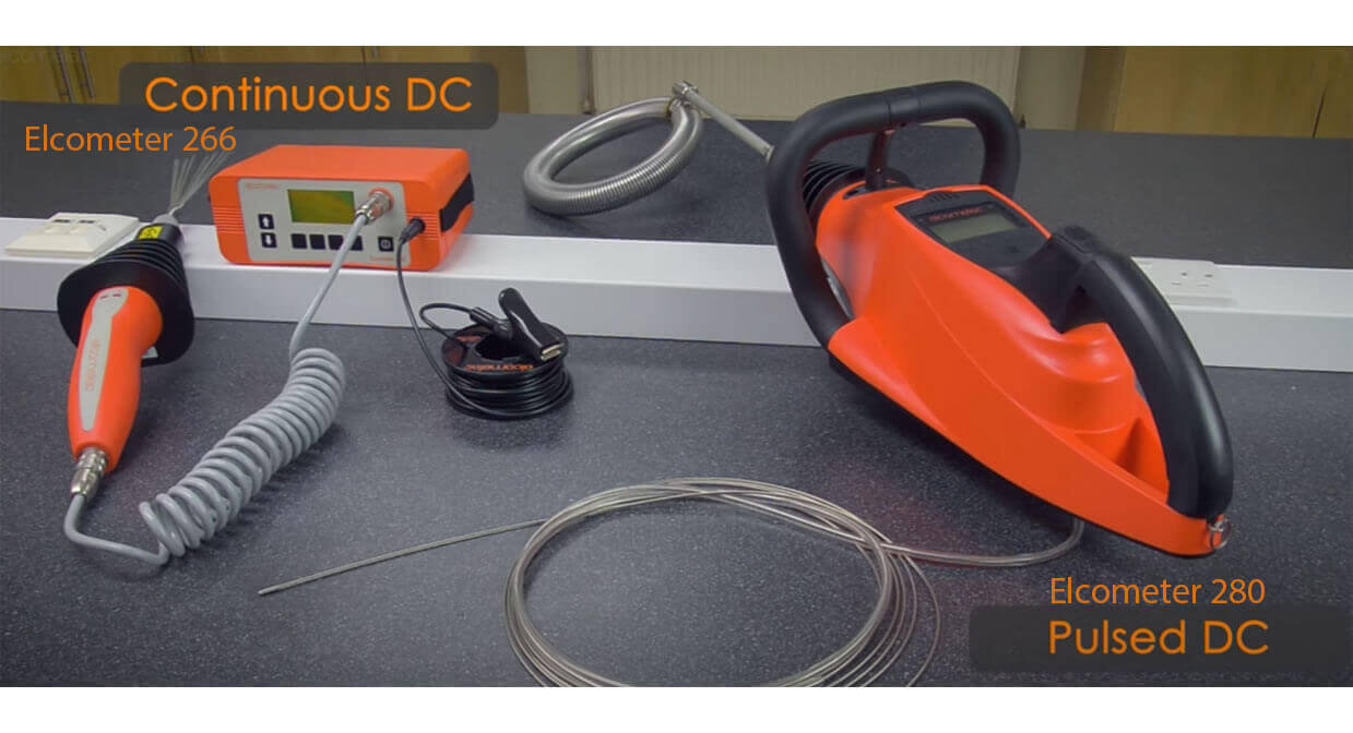
The High Voltage method comes in 2 versions – Continuous DC and Pulsed DC
A. Continuous DC
The voltage is constantly sent to the probe and is used to test insulation coatings on conductive substrates up to 7.5mm (300mils) thick.
Elcometer has two continuous DC detectors: the Elcometer 236, where the high voltage supply is generated within the instrument and sent to the probe handle via a high voltage cable; and the Elcometer 266, where the high voltage supply is generated within the handle, and connected to the instrument via a low voltage cable, resulting in a safer way to test for flaws.
B. Pulsed DC
This stops the probe from building up a charge on the surface, allowing you to safely test for flaws on damp, dirty, or barely conductive coatings.
where the electric impulse is delivered in very short pulses, typically 30 / second (30Hz). Use Elcometer 280 to test coatings up to 25mm (1”). Elcometer 280 is ideal to test large surfaces and pipelines, without constantly having to clip and unclip a return lead every time. There’s also the Elcometer 280 grounding mats and grounding pin, which are ideal for testing on un-grounded pipes.
Testing method 3. The UV Pinhole technique (Elcometer 260)
 This method uses fluorescent coating and inexpensive UV Pinhole Detector Flashlight, which is applied to the surface as a base coat. Once the second coat is applied, pinholes fluoresce when you shine UV light on them.
View more products available in this category
Source video: https://www.youtube.com/watch?v=fQnfhsg_jTU&t=96s

 0 items


