 0 items
Measure Material Thickness from One Side — Even Through Existing Coatings
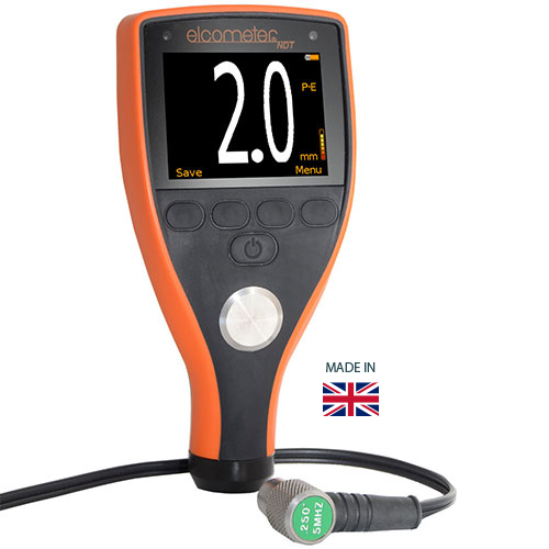
The Elcometer MTG4 Ultrasonic Material Thickness Gauge provides non-destructive thickness measurement when only one side of a component is accessible. Using ultrasonic technology, it measures a wide range of materials, including steel, stainless steel, aluminium, cast iron, plastics, glass, epoxies, and ceramics, making it suitable for corrosion assessment, maintenance inspection, and general material thickness testing.
A major advantage of the MTG4 over basic ultrasonic gauges is its Echo-Echo ThruPaint™ mode. With a compatible coating-thickness transducer, the gauge can ignore the applied coating and determine the thickness of the underlying material without removing the paint. This can save considerable preparation time when inspecting coated tanks, pipes, structures, and equipment.
Measure When Only One Side Is Accessible
Ultrasonic thickness measurement does not require access to the opposite side of the component. The transducer sends an ultrasonic pulse through the material and measures the returning echo from the material boundary, allowing wall thickness to be determined without cutting or dismantling the component.
Measure Through Paint with Echo-Echo ThruPaint™
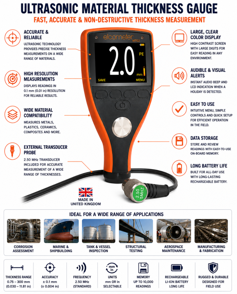
In Echo-Echo ThruPaint™ (EE) mode, the MTG4 measures the substrate while excluding the coating from the displayed thickness. This is particularly useful for inspecting painted steel and other coated components where removing the coating solely to obtain a thickness reading would be undesirable. A compatible damped coating-thickness transducer is required for this mode.
The Elcometer NDT MTG range has a number of measurement modes available to help the user establish the most accurate thickness value. The modes available vary between models but normally increase as the model number increases.
Pulse-Echo Mode for Corrosion and Flaw Inspection
Pulse-Echo (PE) mode measures from the transducer contact surface to the material’s back wall. It is well suited to general wall-thickness inspection and detecting areas where corrosion, pitting, erosion, or material loss may have reduced the original thickness.
Wide 0.63–500mm Measurement Range
In Pulse-Echo mode, the MTG4 has a nominal measurement range of 0.63–500mm (0.025–19.999in), depending on the material and transducer selected. Pulse-Echo accuracy is ±0.1mm from 0.63–19.99mm and ±0.5% from 20–500mm.
39 Pre-Set Material Velocities
Because ultrasonic measurement depends on the speed of sound through the material, correct material selection is essential. The MTG4 simplifies setup with 39 factory-programmed material options, including commonly inspected materials such as aluminium, steel, stainless steel, cast iron, Plexiglas, PVC, polystyrene, and polyurethane.
1-Point Calibration for Known Materials
When an uncoated sample of the material with a known thickness is available, the MTG4 can be calibrated using its 1-point calibration function. This allows the gauge to be matched more closely to the actual material being inspected rather than relying solely on a generic factory material setting.
Velocity Mode for Unknown Materials
The MTG4 also provides Velocity Mode with a range of 1,250–10,000m/s (0.0492–0.3937in/µs). When the thickness of a sample is known, this function can be used to determine its ultrasonic velocity, helping establish the appropriate setting for subsequent measurements of the same material.
USB Data Transfer to ElcoMaster®
Individual measurements can be transferred by USB to ElcoMaster® software for further analysis and inclusion with other coating and inspection data. This provides a practical route from field measurement to documented inspection reporting without requiring a more advanced data-logging gauge.
Choose the Correct Transducer for the Application
The transducer has a major influence on ultrasonic measurement performance. Elcometer offers different dual-element transducers for particular materials, thickness ranges, geometries, and measurement modes. The MTG4-TXC package includes a 5MHz ¼-inch right-angle dual-element transducer, while alternative compatible transducers can be selected for specialized applications.
Designed for Recognized Ultrasonic Thickness Standards
The Elcometer MTG series supports ultrasonic material thickness measurements performed in accordance with recognized standards including ASTM E797, EN 14127, and EN 15317.
SLASH YOUR COSTS BY GETTING A COMPLETE KIT:
LARGER PROJECTS INSPECTION KIT 5 | SEE OTHER KITS AVAILABLE
Key features

Pulsed – Echo Mode (P-E):
Ideal for pit and flaw detection, the total thickness from the base of the transducer to the material density boundary (typically the back-wall) is measured.
larger projects Inspection Kit 5
View Technical Specifications
Product Accessories
Dual & Single Element Transducers |
||||||||||||||||||||||
| Connector Type | Suitable for Measuring | Suitable For | ||||||||||||||||||||
|
Part Number
|
Probe Diameter
|
Probe Configuration
|
Damping
|
ThruPaintTM
|
Potted Right Angle
|
Microdot
|
Cast Iron
|
Plastics
|
Thin Plastics
|
Fiberglass
|
Thin Fiberglass
|
Steel
|
Glass
|
Aluminium
|
Titanium
|
MTG2
|
MTG4
|
MTG6
|
MTG8
|
PTG6
|
PTG8
|
Calibration Certificate
|
1.00 MHz Dual Element Thickness Transducer |
||||||||||||||||||||||
| TXC1M00EP-2 | 1/2″ | Right Angle | S | • | • | • | • | • | • | • | • | • | ||||||||||
2.25 MHz Dual Element Thickness Transducer |
||||||||||||||||||||||
| TXC2M25CP-2 | 1/4″ | Right Angle | S | • | • | • | • | • | • | • | • | • | ||||||||||
| TXC2M25EP-2 | 1/2″ | Right Angle | S | • | • | • | • | • | • | • | • | |||||||||||
3.50 MHz Dual Element Thickness Transducer |
||||||||||||||||||||||
| TXC3M50EP-1 | 1/2″ | Right Angle | CT, HD | • | • | • | • | • | • | • | • | • | • | • | ||||||||
5.00 MHz Dual Element Thickness Transducer |
||||||||||||||||||||||
| TXC5M00BP-4 | 3/16″ | Right Angle | CT, HD | • | • | • | • | • | • | • | • | • | • | |||||||||
| TXC5M00CP-4 | 1/4″ | Right Angle | S | • | • | • | • | • | • | • | • | • | ||||||||||
| TXC5M00BP-6 | 1/4″ | Right Angle | CT, HD | • | • | • | • | • | • | • | • | • | • | |||||||||
| TXC5M00CP-8 | 1/4″ | High Temp | HD | • | • | • | • | • | • | • | • | • | ||||||||||
| TXC5M00EP-3 | 1/2″ | Right Angle | S | • | • | • | • | • | • | • | • | • | ||||||||||
| TXC5M00EP-4 | 1/2″ | Right Angle | CT, HD | • | • | • | • | • | • | • | • | • | • | |||||||||
7.50 MHz Dual Element Thickness Transducer |
||||||||||||||||||||||
| TXC7M50BP-3 | 3/16″ | Right Angle | CT, HD | • | • | • | • | • | • | • | • | • | • | • | ||||||||
| TXC7M50CP-4 | 1/4″ | Right Angle | S | • | • | • | • | • | • | • | • | • | • | |||||||||
| TXC7M50CP-5 | 1/4″ | Right Angle | CT, HD | • | • | • | • | • | • | • | • | • | • | • | ||||||||
10.0 MHz Dual Element Thickness Transducer |
||||||||||||||||||||||
| TXC10M0BP-1 | 3/16″ | Right Angle | S | • | • | • | • | • | • | • | • | |||||||||||
| TXC10M0CP-4 | 1/4″ | Right Angle | S | • | • | • | • | • | • | • | • | |||||||||||
15.0 MHz Single Element Transducer |
||||||||||||||||||||||
| TXC15M0CM | 1/4″ | Right Angle | S | • | • | • | • | • | • | • | • | |||||||||||
20.0 MHz Single Element Transducer |
||||||||||||||||||||||
| TXC20M0CM | 1/4″ | Right Angle | S | • | • | • | • | • | • | • | • | |||||||||||
Delay Lines |
||||||||||||||||||||||
| Each gauge is supplied with 9mm and 12mm acrylic delay lines suitable for measuring on steel, aluminum and titanium. If measuring on thin plastics using Plastic Mode (PLAS), a graphite delay line must be used. These are available to purchase as optional accessories. |
||||||||||||||||||||||
| Part Number | Description | |||||||||||||||||||||
| T92016528 | Acrylic Delay Line; 1/4 Dia x 9mm | |||||||||||||||||||||
| T92016529 | Acrylic Delay Line; 1/4 Dia x 12mm | |||||||||||||||||||||
| T92023853-4 | Graphite Delay Line; 1/4 Dia x 3/16″ | |||||||||||||||||||||
| All transducers are supplied with a calibration certificate HD—Highly damped Transducer CT—Damped Coating Thickness Transducer S—–Standard undamped Transducer |
||||||||||||||||||||||
Frequently Asked Questions
When should I use Echo-Echo ThruPaint™ instead of Pulse-Echo mode?
Use Echo-Echo ThruPaint™ when the substrate is coated and you need the thickness of the underlying material without including the coating in the result. Pulse-Echo is appropriate for uncoated materials and general thickness, pitting, and flaw inspection. Echo-Echo requires a compatible damped coating-thickness transducer.
Why can paint cause an incorrect ultrasonic material thickness reading?
Paint and the substrate normally have different ultrasonic velocities. In a conventional Pulse-Echo measurement, the coating therefore contributes to the ultrasonic travel time and can affect the displayed thickness. Echo-Echo ThruPaint™ isolates the relevant substrate echoes so the coating thickness is excluded from the material measurement.
How do I choose between one of the 39 material presets and 1-point calibration?
A preset is convenient when the material corresponds closely to one of the programmed material types. If you have a representative sample of the actual material with a known thickness, 1-point calibration can compensate for differences between the real material and the nominal ultrasonic velocity of a generic preset.
Can the MTG4 detect corrosion without removing the paint?
It can be used to evaluate remaining material thickness beneath a coating when Echo-Echo ThruPaint™ mode and an appropriate transducer are used. Comparing measurements across a component can help identify areas of wall loss associated with corrosion or erosion without removing sound coating merely to take a thickness reading.
Why is ultrasonic couplant necessary?
Air between the transducer and test surface interferes with transmission of the ultrasonic pulse. Couplant fills the microscopic air gap between the probe and material, allowing ultrasonic energy to pass efficiently into the test piece and produce a usable back-wall echo.
Can the MTG4 measure something other than steel?
Yes. Unlike a steel-only ultrasonic gauge, the MTG4 can be configured for many materials. Its 39 pre-set material velocities and calibration functions support measurement of materials including aluminium, stainless steel, cast iron, plastics, glass, epoxies, and ceramics, provided an appropriate transducer and calibration are used.
How does surface corrosion or roughness affect ultrasonic readings?
Heavy corrosion, pitting, scale, or an irregular contact surface can reduce acoustic coupling and make the returning echo less consistent. The inspection surface should provide sufficient probe contact, and the correct transducer should be selected for the material condition and expected thickness range.
When should I choose the MTG4 instead of the MTG2?
The MTG4 is the better choice when inspection involves coated materials or multiple material types. Compared with the more basic MTG2, it adds Echo-Echo ThruPaint™ measurement, 1-point calibration, material selection from 39 presets, and velocity-related functionality, providing substantially greater flexibility for mixed inspection work.
When would I need an MTG6 or MTG8 instead of the MTG4?
The MTG4 is well suited to straightforward thickness measurements on coated and uncoated materials. More advanced MTG models should be considered when the inspection requires features such as greater measurement resolution, extensive onboard data logging, advanced statistics, scan displays, B-scan visualization, or more sophisticated calibration and reporting functions.
Standards
Can be used in accordance with:
ASTM E797, EN 14127, EN15317

Measure Material Thickness from One Side — Even Through Existing Coatings
The Elcometer MTG4 Ultrasonic Material Thickness Gauge provides non-destructive thickness measurement when only one side of a component is accessible. Using ultrasonic technology, it measures a wide range of materials, including steel, stainless steel, aluminium, cast iron, plastics, glass, epoxies, and ceramics, making it suitable for corrosion assessment, maintenance inspection, and general material thickness testing.
A major advantage of the MTG4 over basic ultrasonic gauges is its Echo-Echo ThruPaint™ mode. With a compatible coating-thickness transducer, the gauge can ignore the applied coating and determine the thickness of the underlying material without removing the paint. This can save considerable preparation time when inspecting coated tanks, pipes, structures, and equipment.
Measure When Only One Side Is Accessible
Ultrasonic thickness measurement does not require access to the opposite side of the component. The transducer sends an ultrasonic pulse through the material and measures the returning echo from the material boundary, allowing wall thickness to be determined without cutting or dismantling the component.
Measure Through Paint with Echo-Echo ThruPaint™
In Echo-Echo ThruPaint™ (EE) mode, the MTG4 measures the substrate while excluding the coating from the displayed thickness. This is particularly useful for inspecting painted steel and other coated components where removing the coating solely to obtain a thickness reading would be undesirable. A compatible damped coating-thickness transducer is required for this mode.
The Elcometer NDT MTG range has a number of measurement modes available to help the user establish the most accurate thickness value. The modes available vary between models but normally increase as the model number increases.
Pulse-Echo Mode for Corrosion and Flaw Inspection
Pulse-Echo (PE) mode measures from the transducer contact surface to the material’s back wall. It is well suited to general wall-thickness inspection and detecting areas where corrosion, pitting, erosion, or material loss may have reduced the original thickness.
Wide 0.63–500mm Measurement Range
In Pulse-Echo mode, the MTG4 has a nominal measurement range of 0.63–500mm (0.025–19.999in), depending on the material and transducer selected. Pulse-Echo accuracy is ±0.1mm from 0.63–19.99mm and ±0.5% from 20–500mm.
39 Pre-Set Material Velocities
Because ultrasonic measurement depends on the speed of sound through the material, correct material selection is essential. The MTG4 simplifies setup with 39 factory-programmed material options, including commonly inspected materials such as aluminium, steel, stainless steel, cast iron, Plexiglas, PVC, polystyrene, and polyurethane.
1-Point Calibration for Known Materials
When an uncoated sample of the material with a known thickness is available, the MTG4 can be calibrated using its 1-point calibration function. This allows the gauge to be matched more closely to the actual material being inspected rather than relying solely on a generic factory material setting.
Velocity Mode for Unknown Materials
The MTG4 also provides Velocity Mode with a range of 1,250–10,000m/s (0.0492–0.3937in/µs). When the thickness of a sample is known, this function can be used to determine its ultrasonic velocity, helping establish the appropriate setting for subsequent measurements of the same material.
USB Data Transfer to ElcoMaster®
Individual measurements can be transferred by USB to ElcoMaster® software for further analysis and inclusion with other coating and inspection data. This provides a practical route from field measurement to documented inspection reporting without requiring a more advanced data-logging gauge.
Choose the Correct Transducer for the Application
The transducer has a major influence on ultrasonic measurement performance. Elcometer offers different dual-element transducers for particular materials, thickness ranges, geometries, and measurement modes. The MTG4-TXC package includes a 5MHz ¼-inch right-angle dual-element transducer, while alternative compatible transducers can be selected for specialized applications.
Designed for Recognized Ultrasonic Thickness Standards
The Elcometer MTG series supports ultrasonic material thickness measurements performed in accordance with recognized standards including ASTM E797, EN 14127, and EN 15317.
SLASH YOUR COSTS BY GETTING A COMPLETE KIT:
LARGER PROJECTS INSPECTION KIT 5 | SEE OTHER KITS AVAILABLE
Key features
Pulsed – Echo Mode (P-E):
Ideal for pit and flaw detection, the total thickness from the base of the transducer to the material density boundary (typically the back-wall) is measured.
larger projects Inspection Kit 5
View Technical Specifications
Product Accessories
Dual & Single Element Transducers |
||||||||||||||||||||||
| Connector Type | Suitable for Measuring | Suitable For | ||||||||||||||||||||
|
Part Number
|
Probe Diameter
|
Probe Configuration
|
Damping
|
ThruPaintTM
|
Potted Right Angle
|
Microdot
|
Cast Iron
|
Plastics
|
Thin Plastics
|
Fiberglass
|
Thin Fiberglass
|
Steel
|
Glass
|
Aluminium
|
Titanium
|
MTG2
|
MTG4
|
MTG6
|
MTG8
|
PTG6
|
PTG8
|
Calibration Certificate
|
1.00 MHz Dual Element Thickness Transducer |
||||||||||||||||||||||
| TXC1M00EP-2 | 1/2″ | Right Angle | S | • | • | • | • | • | • | • | • | • | ||||||||||
2.25 MHz Dual Element Thickness Transducer |
||||||||||||||||||||||
| TXC2M25CP-2 | 1/4″ | Right Angle | S | • | • | • | • | • | • | • | • | • | ||||||||||
| TXC2M25EP-2 | 1/2″ | Right Angle | S | • | • | • | • | • | • | • | • | |||||||||||
3.50 MHz Dual Element Thickness Transducer |
||||||||||||||||||||||
| TXC3M50EP-1 | 1/2″ | Right Angle | CT, HD | • | • | • | • | • | • | • | • | • | • | • | ||||||||
5.00 MHz Dual Element Thickness Transducer |
||||||||||||||||||||||
| TXC5M00BP-4 | 3/16″ | Right Angle | CT, HD | • | • | • | • | • | • | • | • | • | • | |||||||||
| TXC5M00CP-4 | 1/4″ | Right Angle | S | • | • | • | • | • | • | • | • | • | ||||||||||
| TXC5M00BP-6 | 1/4″ | Right Angle | CT, HD | • | • | • | • | • | • | • | • | • | • | |||||||||
| TXC5M00CP-8 | 1/4″ | High Temp | HD | • | • | • | • | • | • | • | • | • | ||||||||||
| TXC5M00EP-3 | 1/2″ | Right Angle | S | • | • | • | • | • | • | • | • | • | ||||||||||
| TXC5M00EP-4 | 1/2″ | Right Angle | CT, HD | • | • | • | • | • | • | • | • | • | • | |||||||||
7.50 MHz Dual Element Thickness Transducer |
||||||||||||||||||||||
| TXC7M50BP-3 | 3/16″ | Right Angle | CT, HD | • | • | • | • | • | • | • | • | • | • | • | ||||||||
| TXC7M50CP-4 | 1/4″ | Right Angle | S | • | • | • | • | • | • | • | • | • | • | |||||||||
| TXC7M50CP-5 | 1/4″ | Right Angle | CT, HD | • | • | • | • | • | • | • | • | • | • | • | ||||||||
10.0 MHz Dual Element Thickness Transducer |
||||||||||||||||||||||
| TXC10M0BP-1 | 3/16″ | Right Angle | S | • | • | • | • | • | • | • | • | |||||||||||
| TXC10M0CP-4 | 1/4″ | Right Angle | S | • | • | • | • | • | • | • | • | |||||||||||
15.0 MHz Single Element Transducer |
||||||||||||||||||||||
| TXC15M0CM | 1/4″ | Right Angle | S | • | • | • | • | • | • | • | • | |||||||||||
20.0 MHz Single Element Transducer |
||||||||||||||||||||||
| TXC20M0CM | 1/4″ | Right Angle | S | • | • | • | • | • | • | • | • | |||||||||||
Delay Lines |
||||||||||||||||||||||
| Each gauge is supplied with 9mm and 12mm acrylic delay lines suitable for measuring on steel, aluminum and titanium. If measuring on thin plastics using Plastic Mode (PLAS), a graphite delay line must be used. These are available to purchase as optional accessories. |
||||||||||||||||||||||
| Part Number | Description | |||||||||||||||||||||
| T92016528 | Acrylic Delay Line; 1/4 Dia x 9mm | |||||||||||||||||||||
| T92016529 | Acrylic Delay Line; 1/4 Dia x 12mm | |||||||||||||||||||||
| T92023853-4 | Graphite Delay Line; 1/4 Dia x 3/16″ | |||||||||||||||||||||
| All transducers are supplied with a calibration certificate HD—Highly damped Transducer CT—Damped Coating Thickness Transducer S—–Standard undamped Transducer |
||||||||||||||||||||||
Frequently Asked Questions
When should I use Echo-Echo ThruPaint™ instead of Pulse-Echo mode?
Use Echo-Echo ThruPaint™ when the substrate is coated and you need the thickness of the underlying material without including the coating in the result. Pulse-Echo is appropriate for uncoated materials and general thickness, pitting, and flaw inspection. Echo-Echo requires a compatible damped coating-thickness transducer.
Why can paint cause an incorrect ultrasonic material thickness reading?
Paint and the substrate normally have different ultrasonic velocities. In a conventional Pulse-Echo measurement, the coating therefore contributes to the ultrasonic travel time and can affect the displayed thickness. Echo-Echo ThruPaint™ isolates the relevant substrate echoes so the coating thickness is excluded from the material measurement.
How do I choose between one of the 39 material presets and 1-point calibration?
A preset is convenient when the material corresponds closely to one of the programmed material types. If you have a representative sample of the actual material with a known thickness, 1-point calibration can compensate for differences between the real material and the nominal ultrasonic velocity of a generic preset.
Can the MTG4 detect corrosion without removing the paint?
It can be used to evaluate remaining material thickness beneath a coating when Echo-Echo ThruPaint™ mode and an appropriate transducer are used. Comparing measurements across a component can help identify areas of wall loss associated with corrosion or erosion without removing sound coating merely to take a thickness reading.
Why is ultrasonic couplant necessary?
Air between the transducer and test surface interferes with transmission of the ultrasonic pulse. Couplant fills the microscopic air gap between the probe and material, allowing ultrasonic energy to pass efficiently into the test piece and produce a usable back-wall echo.
Can the MTG4 measure something other than steel?
Yes. Unlike a steel-only ultrasonic gauge, the MTG4 can be configured for many materials. Its 39 pre-set material velocities and calibration functions support measurement of materials including aluminium, stainless steel, cast iron, plastics, glass, epoxies, and ceramics, provided an appropriate transducer and calibration are used.
How does surface corrosion or roughness affect ultrasonic readings?
Heavy corrosion, pitting, scale, or an irregular contact surface can reduce acoustic coupling and make the returning echo less consistent. The inspection surface should provide sufficient probe contact, and the correct transducer should be selected for the material condition and expected thickness range.
When should I choose the MTG4 instead of the MTG2?
The MTG4 is the better choice when inspection involves coated materials or multiple material types. Compared with the more basic MTG2, it adds Echo-Echo ThruPaint™ measurement, 1-point calibration, material selection from 39 presets, and velocity-related functionality, providing substantially greater flexibility for mixed inspection work.
When would I need an MTG6 or MTG8 instead of the MTG4?
The MTG4 is well suited to straightforward thickness measurements on coated and uncoated materials. More advanced MTG models should be considered when the inspection requires features such as greater measurement resolution, extensive onboard data logging, advanced statistics, scan displays, B-scan visualization, or more sophisticated calibration and reporting functions.
Standards
Can be used in accordance with:
ASTM E797, EN 14127, EN15317