 0 items
Map Corrosion, Evaluate Remaining Wall Thickness, and Record Complex Ultrasonic Inspections
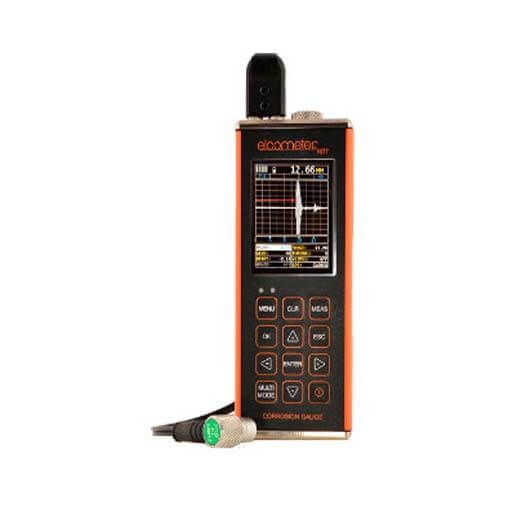
The Elcometer NDT CG100ABDL+ Ultrasonic Corrosion Mapping Gauge is an advanced thickness and flaw-inspection instrument designed for demanding corrosion assessment. It combines multiple ultrasonic measurement modes, A-Scan waveform analysis, high-speed scanning, grid data logging, adjustable gain, gates, and extensive calibration controls in a portable handheld gauge.
With measurement modes for substrates, coatings, and measurements through paint, the CG100ABDL+ can evaluate coated and uncoated components while providing the detailed waveform information needed for challenging materials and inspection conditions. It stores up to 210,000 thickness readings, or 8,000 readings complete with A/B-Scan images and gauge settings.
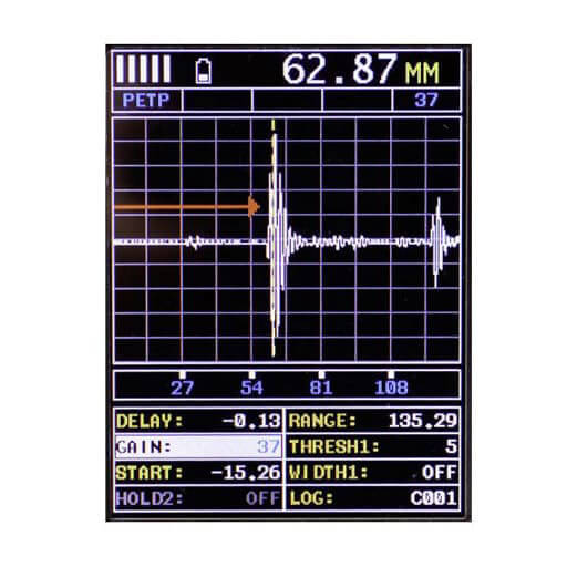
See the Ultrasonic Signal with A-Scan
The CG100ABDL+ provides A-Scan waveform displays in positive rectified, negative rectified, and full waveform RF formats. Instead of relying solely on a numerical thickness value, inspectors can evaluate the returning ultrasonic signal and adjust the measurement setup when surface condition, material structure, geometry, or corrosion makes interpretation more difficult.
Measure Substrate and Coating Thickness
The gauge supports Pulse-Echo (PE), Pulse-Echo Temperature Compensated (PETP), Echo-Echo ThruPaint™ (EE), Echo-Echo Verify (EEV), Coating Only (CT), and Pulse-Echo Coating (PECT) measurement modes. This allows the instrument to be configured for a much wider range of corrosion and coating inspection tasks than a basic ultrasonic thickness gauge.
Measure Through Existing Paint
Echo-Echo ThruPaint™ mode can determine underlying material thickness without including a compatible coating in the result. This can reduce the need to remove intact paint simply to assess remaining wall thickness during corrosion surveys.
Measure Up to 508mm in Pulse-Echo Mode
Pulse-Echo and Pulse-Echo Temperature Compensated modes provide a measurement range of 0.63–508mm (0.025–19.999in). Echo-Echo mode covers 1.27–102mm (0.050–4.000in). Measurement resolution is 0.01mm (0.001in), with stated measurement accuracy of ±0.01mm (±0.001in).
Scan at Up to 32 Readings per Second
High-speed Scan Mode captures up to 32 readings per second, helping inspectors search larger areas for localized wall loss rather than relying exclusively on isolated measurement points. Differential and minimum-thickness alarm modes provide additional tools for recognizing areas that deviate from specified or expected thickness.
Control Difficult Signals with Adjustable Gain
Automatic Gain Control (AGC) simplifies routine measurement, while manual gain adjustment allows experienced inspectors to optimize the received echo for different materials and inspection conditions. The instrument provides a wide gain range and Time Corrected Gain (TCG) to compensate for ultrasonic attenuation as sound travels through the material.
Isolate Relevant Echoes with Three Adjustable Gates
Three fully adjustable gates allow the inspector to define where the gauge evaluates the ultrasonic waveform. Gate start, stop, width, and threshold can be controlled to help bypass unwanted surface echoes or material noise and focus measurement on the relevant signal.
Adjust Threshold for Weak Echoes
Threshold adjustment changes the signal level required for detection. This provides additional control when inspecting materials or conditions that produce lower-amplitude echoes and helps experienced operators distinguish meaningful signals from background noise.
Map Large Components with Grid Logging
Measurements can be organized sequentially or in grids so each reading corresponds to a defined inspection location. Grid-based logging is particularly useful for systematic corrosion mapping of tanks, vessels, pipelines, and other large components. Inaccessible locations can be marked as OBSTRUCT without disrupting the inspection sequence.
Store Readings, Waveforms, and Gauge Settings
The CG100ABDL+ can store up to 210,000 coating, material, minimum, or maximum thickness readings. For inspections requiring greater traceability, up to 8,000 records can be stored together with A/B-Scan images and gauge settings. Alphanumeric batch identification helps organize measurements by component, location, or inspection project.
Save Setups for Repeated Inspection Work
The gauge includes six factory setups and up to 64 user-defined setups. Configurations can be stored for different materials, transducers, components, or inspection procedures and transferred to and from a PC archive, reducing setup time during recurring inspections.
 CG100 ABDL+ is ideal for all applications: it features automatic gain control (AGC) for ease of use or manual adjustment (-30dB to 70dB) to increase the amplitude of the received echo to suit the material properties, the .
The time-corrected gain (TCG) feature automatically compensates for sound attenuation through a material, further increasing the performance of the gauge.
Built-in Gates allow users to set the measurement parameters either on or between waveforms, bypassing any surface echoes or noise from the material.
Threshold adjustment allows users to adjust the sensitivity of the gauge to detect signals with lower amplitudes.
The CG100ABDL+ thickness gauge stores up to 16,000 readings with individual waveforms in alphanumeric batches and full data logging through RS232 data output to Elcometer NDT data management software.
With its high-contrast color display, the CG100ABDL+ thickness gauge has a refresh rate of 120Hz providing users with an instant measurement response.
Advantages
- Range of display & measurement options: Pulse-Echo, Echo-Echo, Pulse-Echo Temp, Comp Mode (PETP), Coating Only Mode (CT), Pulse-Echo Coating Mode (PECT)
- Adjustable gain: -30dB to 70dB range
- Automatic gain control (AGC)
- Time-corrected gain (TCG)
- Gate control
- Threshold adjustment
- 64 User-defined setups
- Multiple language display
- Multiple calibrations and material selection options
- High-speed scan mode: 32 readings per second
- Differential and minimal thickness alarm modes
- Data output and storage: 16,000 readings and waveforms or B-Scans
- Data management software
Specifications – ultrasonic corrosion mapping gauge
| Model & Part Number | CG100ABDL Corrosion Thickness Gauge |
| Material thickness digits display | – |
| B-Scan cross-sectional display | – |
| Combined B-Scan and digits display | – |
| Scan bar display | – |
| Coating thickness display | – |
| A-Scan Display | + Rectified, – Rectified, Full Waveform (RF) |
| Measurement Mode | PE, PETP (Temp Compensation), EE (ThruPaint™), EEV, CT (Coating) & PECT |
| Measurement Rate Manual: Scan mode Scan bar display |
4 readings per second 32 readings per second 6 readings per second |
| Measuring Range | PE: 0.63 – 508mm (0.025 – 19.999 inches) PETP: 0.63 – 508mm (0.025 – 19.999 inches) EE: 1.27 – 102mm (0.050 – 4.000 inches) EEV: 1.27 – 25.4mm (0.050 – 1.000 inch) CT: 12.7 – 254μm (0.0005 – 0.100 inch) PECT: 0.63 – 508mm (0.025 – 19.999 inches) PECT: 0.01 – 2.54mm (0.0005 – 0.100 inch) |
| Measurement Accuracy | ±0.01mm (±0.001 inch) |
| Measurement Resolution | 0.01mm (0.001 inch) |
| Velocity Calibration Range | 1250 – 9,999m/s (0.0492 – 0.3936in/ms) |
| Additional Features: High speed scan mode |
– |
| Differential mode | – |
| Limit alarm mode | – |
| B-Scan display speed | adjustable display speed |
| Flaw mode | Basic prove-up flaw detection using single element angle beam transducers |
| Calibration setups | 6 factory & 64 user-definable setups transferrable to and from a PC archive |
| Gates | 3 fully adjustable gates: start, stop, width & threshold |
| Damping | adjustable; impedance matching for optimizing transducer performance |
| Pulser type | dual 200-volt square wave pulses with adjustable pulse width (spike, thin, wide) and 50-volt cut/boost for greater penetration |
| Gain | manual, automatic gain control (AGC) with 110dB range (limited), time corrected gain (TCG) |
| Timing | precision 25MHz TCXO with a single shot 100MHz 8bit ultra-low-power 8-bit digitizer |
| Data logging | 8,000 with A/B-scan image & gauge settings 210,000 – coating, material, min, max thickness sequential and grid logging Alphanumeric batch identification OBSTRUCT indicates inaccessible locations |
| Calibration Options | single, two-point, velocity & material type |
| Transducer Probe Type | dual element & flaw prove up |
| Transducer Frequency Range | 1 – 10MHz |
| Transducer recognition | automatic & manual – selectable from a list |
| V-path / dual path error correction | automatic |
| Probe zero | automatic & manual (via integrated probe disk) |
| Display | 1/4 VGA AMOLED color display 57.6 x 43.2mm (2.27 x 1.78inch) viewable area |
| Display Refresh Rate | 120Hz |
| Units (selectable) | mm or inches |
| Backlight | adjustable brightness |
| Repeatability / Stability Indicator | – |
| Battery Type | 3 x AA alkaline |
| Battery Life (approximate) | 25 hours |
| Low Battery Indicator | – |
| Battery Save Mode | auto |
| Operating Temperature | -10 to 60ºC (14 to 140ºF) |
| Size (w x h x d) | 63.5 x 165.0 x 31.5mm (2.5 x 6.5 x 1.24 inches) |
| Weight (including batteries) | 383g (13.5oz) |
| Aluminum case design with the gasket-sealed end caps, waterproof membrane keypad |
– |
| Transducer Connector Type | LEMO |
| RS232 Interface | Bi-directional |
| Packing List | Elcometer NDT CG100ABDL+ gauge, couplant, carry case, user manual, test certificate, 3 x AA batteries, software, transfer cable |
Frequently Asked Questions
When is the CG100ABDL+ preferable to a simpler ultrasonic thickness gauge?
The CG100ABDL+ is most useful when inspection conditions require more than straightforward numerical wall-thickness readings. A-Scan waveform analysis, adjustable gain, TCG, gates, threshold control, multiple measurement modes, and extensive data logging give experienced inspectors greater control when evaluating corrosion, difficult materials, coatings, or complex ultrasonic signals.
Why is an A-Scan useful during corrosion inspection?
A numerical display tells the inspector what thickness the instrument has calculated; an A-Scan shows the ultrasonic echoes used to produce that result. Viewing the waveform can help determine whether the gauge is responding to the intended back-wall echo or to another feature such as noise, geometry, coating interfaces, or corrosion-related indications.
When should I use Echo-Echo ThruPaint™ instead of Pulse-Echo?
Echo-Echo ThruPaint™ is useful when measuring the remaining substrate thickness beneath a compatible coating without including that coating in the result. Pulse-Echo is generally appropriate for uncoated materials and provides the gauge’s widest material-thickness range. The appropriate transducer and calibration must be selected for the application.
What is the advantage of Pulse-Echo Coating Mode?
Pulse-Echo Coating (PECT) mode allows coating and material thickness information to be obtained as part of the ultrasonic inspection. This is useful when both the protective coating and underlying component need to be evaluated rather than simply ignoring the coating with a ThruPaint™ measurement.
Why would an inspector use Time Corrected Gain?
Ultrasonic signals lose energy as they travel through material. Time Corrected Gain compensates for this attenuation by changing amplification according to the signal’s travel time, helping maintain useful echo response at different depths and improving inspection performance in applications where attenuation is significant.
How do gates help when corrosion produces a complicated waveform?
Gates restrict signal evaluation to selected regions of the waveform. When surface echoes, geometry, noise, or other indications appear outside the area of interest, properly configured gates can help the instrument focus on the echo relevant to the required measurement or flaw assessment.
Why is minimum thickness more important than average thickness when mapping corrosion?
Corrosion and pitting can create small areas that are considerably thinner than the surrounding material. An acceptable average thickness can therefore conceal a potentially significant localized thin spot. High-speed scanning and minimum-thickness functions help inspectors search for these areas rather than relying solely on widely spaced individual readings.
How does grid logging improve repeat corrosion surveys?
A grid associates readings with defined physical locations on the inspected component. When the same grid is used during later inspections, measurements can be compared by location, making it easier to identify areas where wall loss is progressing and to build a more systematic corrosion-monitoring history.
Can the CG100ABDL+ perform flaw detection as well as thickness measurement?
Yes. Elcometer specifies a basic prove-up flaw-detection capability using compatible single-element angle-beam transducers. This extends the instrument beyond routine corrosion thickness measurement, although specialized ultrasonic flaw evaluation still requires appropriate probes, procedures, calibration, and operator expertise.
How do I choose the correct transducer for corrosion mapping?
Transducer selection depends on factors including material, expected thickness, surface condition, geometry, temperature, and whether ThruPaint™ measurement is required. Elcometer offers CG100-compatible dual-element probes in different frequencies, diameters, damping characteristics, connector configurations, and high-temperature versions, so the probe should be matched to the actual inspection rather than selected solely by gauge model.

Map Corrosion, Evaluate Remaining Wall Thickness, and Record Complex Ultrasonic Inspections
The Elcometer NDT CG100ABDL+ Ultrasonic Corrosion Mapping Gauge is an advanced thickness and flaw-inspection instrument designed for demanding corrosion assessment. It combines multiple ultrasonic measurement modes, A-Scan waveform analysis, high-speed scanning, grid data logging, adjustable gain, gates, and extensive calibration controls in a portable handheld gauge.
With measurement modes for substrates, coatings, and measurements through paint, the CG100ABDL+ can evaluate coated and uncoated components while providing the detailed waveform information needed for challenging materials and inspection conditions. It stores up to 210,000 thickness readings, or 8,000 readings complete with A/B-Scan images and gauge settings.
See the Ultrasonic Signal with A-Scan
The CG100ABDL+ provides A-Scan waveform displays in positive rectified, negative rectified, and full waveform RF formats. Instead of relying solely on a numerical thickness value, inspectors can evaluate the returning ultrasonic signal and adjust the measurement setup when surface condition, material structure, geometry, or corrosion makes interpretation more difficult.
Measure Substrate and Coating Thickness
The gauge supports Pulse-Echo (PE), Pulse-Echo Temperature Compensated (PETP), Echo-Echo ThruPaint™ (EE), Echo-Echo Verify (EEV), Coating Only (CT), and Pulse-Echo Coating (PECT) measurement modes. This allows the instrument to be configured for a much wider range of corrosion and coating inspection tasks than a basic ultrasonic thickness gauge.
Measure Through Existing Paint
Echo-Echo ThruPaint™ mode can determine underlying material thickness without including a compatible coating in the result. This can reduce the need to remove intact paint simply to assess remaining wall thickness during corrosion surveys.
Measure Up to 508mm in Pulse-Echo Mode
Pulse-Echo and Pulse-Echo Temperature Compensated modes provide a measurement range of 0.63–508mm (0.025–19.999in). Echo-Echo mode covers 1.27–102mm (0.050–4.000in). Measurement resolution is 0.01mm (0.001in), with stated measurement accuracy of ±0.01mm (±0.001in).
Scan at Up to 32 Readings per Second
High-speed Scan Mode captures up to 32 readings per second, helping inspectors search larger areas for localized wall loss rather than relying exclusively on isolated measurement points. Differential and minimum-thickness alarm modes provide additional tools for recognizing areas that deviate from specified or expected thickness.
Control Difficult Signals with Adjustable Gain
Automatic Gain Control (AGC) simplifies routine measurement, while manual gain adjustment allows experienced inspectors to optimize the received echo for different materials and inspection conditions. The instrument provides a wide gain range and Time Corrected Gain (TCG) to compensate for ultrasonic attenuation as sound travels through the material.
Isolate Relevant Echoes with Three Adjustable Gates
Three fully adjustable gates allow the inspector to define where the gauge evaluates the ultrasonic waveform. Gate start, stop, width, and threshold can be controlled to help bypass unwanted surface echoes or material noise and focus measurement on the relevant signal.
Adjust Threshold for Weak Echoes
Threshold adjustment changes the signal level required for detection. This provides additional control when inspecting materials or conditions that produce lower-amplitude echoes and helps experienced operators distinguish meaningful signals from background noise.
Map Large Components with Grid Logging
Measurements can be organized sequentially or in grids so each reading corresponds to a defined inspection location. Grid-based logging is particularly useful for systematic corrosion mapping of tanks, vessels, pipelines, and other large components. Inaccessible locations can be marked as OBSTRUCT without disrupting the inspection sequence.
Store Readings, Waveforms, and Gauge Settings
The CG100ABDL+ can store up to 210,000 coating, material, minimum, or maximum thickness readings. For inspections requiring greater traceability, up to 8,000 records can be stored together with A/B-Scan images and gauge settings. Alphanumeric batch identification helps organize measurements by component, location, or inspection project.
Save Setups for Repeated Inspection Work
The gauge includes six factory setups and up to 64 user-defined setups. Configurations can be stored for different materials, transducers, components, or inspection procedures and transferred to and from a PC archive, reducing setup time during recurring inspections.
CG100 ABDL+ is ideal for all applications: it features automatic gain control (AGC) for ease of use or manual adjustment (-30dB to 70dB) to increase the amplitude of the received echo to suit the material properties, the .
The time-corrected gain (TCG) feature automatically compensates for sound attenuation through a material, further increasing the performance of the gauge.
Built-in Gates allow users to set the measurement parameters either on or between waveforms, bypassing any surface echoes or noise from the material.
Threshold adjustment allows users to adjust the sensitivity of the gauge to detect signals with lower amplitudes.
The CG100ABDL+ thickness gauge stores up to 16,000 readings with individual waveforms in alphanumeric batches and full data logging through RS232 data output to Elcometer NDT data management software.
With its high-contrast color display, the CG100ABDL+ thickness gauge has a refresh rate of 120Hz providing users with an instant measurement response.
Advantages
- Range of display & measurement options: Pulse-Echo, Echo-Echo, Pulse-Echo Temp, Comp Mode (PETP), Coating Only Mode (CT), Pulse-Echo Coating Mode (PECT)
- Adjustable gain: -30dB to 70dB range
- Automatic gain control (AGC)
- Time-corrected gain (TCG)
- Gate control
- Threshold adjustment
- 64 User-defined setups
- Multiple language display
- Multiple calibrations and material selection options
- High-speed scan mode: 32 readings per second
- Differential and minimal thickness alarm modes
- Data output and storage: 16,000 readings and waveforms or B-Scans
- Data management software
Specifications – ultrasonic corrosion mapping gauge
| Model & Part Number | CG100ABDL Corrosion Thickness Gauge |
| Material thickness digits display | – |
| B-Scan cross-sectional display | – |
| Combined B-Scan and digits display | – |
| Scan bar display | – |
| Coating thickness display | – |
| A-Scan Display | + Rectified, – Rectified, Full Waveform (RF) |
| Measurement Mode | PE, PETP (Temp Compensation), EE (ThruPaint™), EEV, CT (Coating) & PECT |
| Measurement Rate Manual: Scan mode Scan bar display |
4 readings per second 32 readings per second 6 readings per second |
| Measuring Range | PE: 0.63 – 508mm (0.025 – 19.999 inches) PETP: 0.63 – 508mm (0.025 – 19.999 inches) EE: 1.27 – 102mm (0.050 – 4.000 inches) EEV: 1.27 – 25.4mm (0.050 – 1.000 inch) CT: 12.7 – 254μm (0.0005 – 0.100 inch) PECT: 0.63 – 508mm (0.025 – 19.999 inches) PECT: 0.01 – 2.54mm (0.0005 – 0.100 inch) |
| Measurement Accuracy | ±0.01mm (±0.001 inch) |
| Measurement Resolution | 0.01mm (0.001 inch) |
| Velocity Calibration Range | 1250 – 9,999m/s (0.0492 – 0.3936in/ms) |
| Additional Features: High speed scan mode |
– |
| Differential mode | – |
| Limit alarm mode | – |
| B-Scan display speed | adjustable display speed |
| Flaw mode | Basic prove-up flaw detection using single element angle beam transducers |
| Calibration setups | 6 factory & 64 user-definable setups transferrable to and from a PC archive |
| Gates | 3 fully adjustable gates: start, stop, width & threshold |
| Damping | adjustable; impedance matching for optimizing transducer performance |
| Pulser type | dual 200-volt square wave pulses with adjustable pulse width (spike, thin, wide) and 50-volt cut/boost for greater penetration |
| Gain | manual, automatic gain control (AGC) with 110dB range (limited), time corrected gain (TCG) |
| Timing | precision 25MHz TCXO with a single shot 100MHz 8bit ultra-low-power 8-bit digitizer |
| Data logging | 8,000 with A/B-scan image & gauge settings 210,000 – coating, material, min, max thickness sequential and grid logging Alphanumeric batch identification OBSTRUCT indicates inaccessible locations |
| Calibration Options | single, two-point, velocity & material type |
| Transducer Probe Type | dual element & flaw prove up |
| Transducer Frequency Range | 1 – 10MHz |
| Transducer recognition | automatic & manual – selectable from a list |
| V-path / dual path error correction | automatic |
| Probe zero | automatic & manual (via integrated probe disk) |
| Display | 1/4 VGA AMOLED color display 57.6 x 43.2mm (2.27 x 1.78inch) viewable area |
| Display Refresh Rate | 120Hz |
| Units (selectable) | mm or inches |
| Backlight | adjustable brightness |
| Repeatability / Stability Indicator | – |
| Battery Type | 3 x AA alkaline |
| Battery Life (approximate) | 25 hours |
| Low Battery Indicator | – |
| Battery Save Mode | auto |
| Operating Temperature | -10 to 60ºC (14 to 140ºF) |
| Size (w x h x d) | 63.5 x 165.0 x 31.5mm (2.5 x 6.5 x 1.24 inches) |
| Weight (including batteries) | 383g (13.5oz) |
| Aluminum case design with the gasket-sealed end caps, waterproof membrane keypad |
– |
| Transducer Connector Type | LEMO |
| RS232 Interface | Bi-directional |
| Packing List | Elcometer NDT CG100ABDL+ gauge, couplant, carry case, user manual, test certificate, 3 x AA batteries, software, transfer cable |
Frequently Asked Questions
When is the CG100ABDL+ preferable to a simpler ultrasonic thickness gauge?
The CG100ABDL+ is most useful when inspection conditions require more than straightforward numerical wall-thickness readings. A-Scan waveform analysis, adjustable gain, TCG, gates, threshold control, multiple measurement modes, and extensive data logging give experienced inspectors greater control when evaluating corrosion, difficult materials, coatings, or complex ultrasonic signals.
Why is an A-Scan useful during corrosion inspection?
A numerical display tells the inspector what thickness the instrument has calculated; an A-Scan shows the ultrasonic echoes used to produce that result. Viewing the waveform can help determine whether the gauge is responding to the intended back-wall echo or to another feature such as noise, geometry, coating interfaces, or corrosion-related indications.
When should I use Echo-Echo ThruPaint™ instead of Pulse-Echo?
Echo-Echo ThruPaint™ is useful when measuring the remaining substrate thickness beneath a compatible coating without including that coating in the result. Pulse-Echo is generally appropriate for uncoated materials and provides the gauge’s widest material-thickness range. The appropriate transducer and calibration must be selected for the application.
What is the advantage of Pulse-Echo Coating Mode?
Pulse-Echo Coating (PECT) mode allows coating and material thickness information to be obtained as part of the ultrasonic inspection. This is useful when both the protective coating and underlying component need to be evaluated rather than simply ignoring the coating with a ThruPaint™ measurement.
Why would an inspector use Time Corrected Gain?
Ultrasonic signals lose energy as they travel through material. Time Corrected Gain compensates for this attenuation by changing amplification according to the signal’s travel time, helping maintain useful echo response at different depths and improving inspection performance in applications where attenuation is significant.
How do gates help when corrosion produces a complicated waveform?
Gates restrict signal evaluation to selected regions of the waveform. When surface echoes, geometry, noise, or other indications appear outside the area of interest, properly configured gates can help the instrument focus on the echo relevant to the required measurement or flaw assessment.
Why is minimum thickness more important than average thickness when mapping corrosion?
Corrosion and pitting can create small areas that are considerably thinner than the surrounding material. An acceptable average thickness can therefore conceal a potentially significant localized thin spot. High-speed scanning and minimum-thickness functions help inspectors search for these areas rather than relying solely on widely spaced individual readings.
How does grid logging improve repeat corrosion surveys?
A grid associates readings with defined physical locations on the inspected component. When the same grid is used during later inspections, measurements can be compared by location, making it easier to identify areas where wall loss is progressing and to build a more systematic corrosion-monitoring history.
Can the CG100ABDL+ perform flaw detection as well as thickness measurement?
Yes. Elcometer specifies a basic prove-up flaw-detection capability using compatible single-element angle-beam transducers. This extends the instrument beyond routine corrosion thickness measurement, although specialized ultrasonic flaw evaluation still requires appropriate probes, procedures, calibration, and operator expertise.
How do I choose the correct transducer for corrosion mapping?
Transducer selection depends on factors including material, expected thickness, surface condition, geometry, temperature, and whether ThruPaint™ measurement is required. Elcometer offers CG100-compatible dual-element probes in different frequencies, diameters, damping characteristics, connector configurations, and high-temperature versions, so the probe should be matched to the actual inspection rather than selected solely by gauge model.