1 item


With all the functionality of the top-of-the-range material thickness gauge, the FD700DL+ flaw detector, when in flaw detection mode offers a variety of tool kits that enable fast and accurate flaw detection, ideal for weld inspection, forgings, or composite material testing.
Tool kits include:
- TRIG enabling flaw detection in both surface distance and depth from the transducer.
- DAC for the creation of DAC curves which are used to inform the operator of the size of any given flaw at any depth.
- AWS function provides automatic defect sizing in accordance with AWS D1.1 structural welding code.
- AVG/DGS allows automatic defect sizing using probe data, storing up to 64 custom setups.
- TCG (time corrected gain) increases gain as time increases, in order to achieve an over all level of sensitivity for the same flaw/reflector at different distances.
What makes Elcometer NDT FD700DL+ so efficient
- Exceptional visibility in sunlight (AMOLED) colour VGA display (320×240 pixels)
- Sizing Toolkits: DAC, AWS, TCG, DGS
- P.R.F. 8 to 333 Hz, adjustable
- Screen Refresh Rate: Adjustable 60 & 120 Hz
- Detection: Z-Cross, Flank & Peak
- Automatic: probe zero, probe recognition, and temperature compensation
- Measurement: Variety of modes to address a number of applications
- Large data storage with multiple formats: Alpha numeric grid and sequential w/auto identifier
- Up to 12 hours of battery life
- Data management software
| Model & Part Number | FD700DL+ Flaw Detection Gauge |
| Material thickness digits display | – |
| B-Scan cross-sectional display | – |
| B-Scan with digits display | – |
| Scan bar display | – |
| Coating thickness display | – |
| A-Scan display | + Rectified, – Rectified, Full Waveform (RF) |
| Flaw detection modes | TRIG, DAC, AWS, TCG, Zero Crossing, Flank, Peak |
| Measurement Mode | PE, PETP (Temp Compensation), EE (ThruPaint™), EEV, CT (Coating) & PECT |
| Measurement Rate (Thickness Mode) Manual: Scan mode Scan bar display |
4 readings per second 32 readings per second 6 readings per second |
| Measuring Range | PE: 0.63 – 30480mm (0.025 – 1,200 inches) PETP: 0.63 – 30480mm (0.025 – 1,200 inches) EE: 1.27 – 102mm (0.050 – 4.000 inches) EEV: 1.27 – 25.4mm (0.050 – 1.000 inch) CT: 0.01 – 2.54mm (0.0005 – 0.100 inch) PECT: 0.63 – 30480mm (0.025 – 1,200 inches) PECT: 0.01 – 2.54mm (0.0005 – 0.100 inch) |
| Measurement Accuracy | ±0.01mm (±0.001 inch) |
| Measurement Resolution | 0.01mm (0.001 inch) |
| Velocity Calibration Range | 256 – 16,000m/s (0.0100 – 0.6300in/ms) |
| Additional Features: | |
| High speed scan mode | – |
| Differential mode | – |
| Limit alarm mode | – |
| B-Scan display speed | adjustable display speed |
| Calibration setups | 6 factory & 64 user-definable setups transferrable to and from a PC archive |
| Gates | 3 fully adjustable gates: start, stop, width & threshold |
| Damping | adjustable; impedance matching for optimizing transducer performance |
| Pulser type | dual 200 Volt square wave pulsers with adjustable pulse width (spike, thin, wide) and 50 Volt cut/boost for greater penetration |
| Gain | manual, automatic gain control (AGC) with 110dB range with 0.2dB resolution |
| Timing | precision 25MHz TCXO with a single shot 100MHz 8bit ultra-low-power 8-bit digitizer |
| Data logging | – 8,000 with A/B-scan image & gauge settings – 210,000 – coating, material, min, max thickness – sequential and grid logging – Alphanumeric batch identification – OBSTRUCT indicates inaccessible locations |
| Calibration Options | single, two-point, velocity & material type |
| Transducer recognition | automatic |
| V-path / dual path error correction | automatic |
| Probe zero | automatic |
| Flaw Detection Mode Features | |
| Automatic Calibration: |
Longitudinal (straight), or Shear (angle) |
| Probe Types: | Single Contact, Dual, Delay & Angle |
| Material Velocity Table: | Contains longitudinal and shear velocities for a variety of material types |
| TRIG | Trigonometric display of beam path, depth, surface distance, and curved surface correction. Used with angle beam transducers |
| DAC | Up to 8 points may be entered and used to digitally draw a DAC curve. Reference -2, -6, -10, (-6/-12), (-6/-14), (-2/-6/-10) dB. Amplitude displayed in %DAC, dB, or %FSH |
| AWS | Automatic defect sizing in accordance with AWS D1.1 structural welding code. |
| AVG/DGS | Automatic defect sizing using a probe data. Stores up to 64 custom setups |
| TCG | Time corrected gain. 50 dB dynamic range, 20 dB per microsecond, up to 8 points for curve definition |
| Detection Modes | Zero-Crossing, Flank and Peak |
| Display Freeze | Hold current waveform on screen |
| Peak Memory | Captures peak signal amplitude. |
| P.R.F | 8 to 333Hz in selectable steps (8, 16, 32, 66, 125, 250, 333Hz) |
| Pulse Width | 40 to 400 ns. Selectable step options 40, 80 & 400 ns (labeled spike, thin & wide) |
| Frequency Bands | FD700+ & FD700DL+: Broadband 1.8 – 19 MHz (-3dB). FD700DL+: Three narrow bands at 2MHz, 5MHz, 10MHz |
| Horizontal Linearity | +/- 0.4% FSW |
| Vertical Linearity | +/- 1% FSH |
| Amplifier Linearity | +/- 1 dB |
| Amplitude Measurement | 0 to 100% FSH, with 1% resolution |
| Delay | 0 – 999in (25,375mm) at steel velocity |
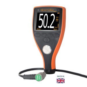
| Display | 1/4″ VGA AMOLED color display 57.6 x 43.2mm (2.27 x 1.78inch) viewable area |
| Display Refresh Rate | 120Hz |
| Units (selectable) | mm or inches |
| Backlight | adjustable brightness |
| Repeatability / Stability Indicator | – |
| Battery Type | 3 x AA alkaline |
| Battery Life (approximate) |
12 hours |
| Low Battery Indicator | – |
| Battery Save Mode | auto |
| Operating Temperature | -10 to 60ºC (14 to 140ºF) |
| Size (w x h x d) | 63.5 x 165.0 x 31.5mm (2.5 x 6.5 x 1.24 inches) |
| Weight (including batteries) | 397g (14oz) |
| Case Design | Aluminum case design with gasket-sealed end caps, waterproof membrane keypad |
| Transducer Connector Type | LEMO |
| RS232 Interface | Bi-directional |
| Packing List | Elcometer FD700DL+ flaw detection gauge, couplant, carry case, user manual, test certificate, 3 x AA batteries, software, transfer cable |
With all the functionality of the top-of-the-range material thickness gauge, the FD700DL+ flaw detector, when in flaw detection mode offers a variety of tool kits that enable fast and accurate flaw detection, ideal for weld inspection, forgings, or composite material testing.
Tool kits include:
- TRIG enabling flaw detection in both surface distance and depth from the transducer.
- DAC for the creation of DAC curves which are used to inform the operator of the size of any given flaw at any depth.
- AWS function provides automatic defect sizing in accordance with AWS D1.1 structural welding code.
- AVG/DGS allows automatic defect sizing using probe data, storing up to 64 custom setups.
- TCG (time corrected gain) increases gain as time increases, in order to achieve an over all level of sensitivity for the same flaw/reflector at different distances.
What makes Elcometer NDT FD700DL+ so efficient
- Exceptional visibility in sunlight (AMOLED) colour VGA display (320×240 pixels)
- Sizing Toolkits: DAC, AWS, TCG, DGS
- P.R.F. 8 to 333 Hz, adjustable
- Screen Refresh Rate: Adjustable 60 & 120 Hz
- Detection: Z-Cross, Flank & Peak
- Automatic: probe zero, probe recognition, and temperature compensation
- Measurement: Variety of modes to address a number of applications
- Large data storage with multiple formats: Alpha numeric grid and sequential w/auto identifier
- Up to 12 hours of battery life
- Data management software
| Model & Part Number | FD700DL+ Flaw Detection Gauge |
| Material thickness digits display | – |
| B-Scan cross-sectional display | – |
| B-Scan with digits display | – |
| Scan bar display | – |
| Coating thickness display | – |
| A-Scan display | + Rectified, – Rectified, Full Waveform (RF) |
| Flaw detection modes | TRIG, DAC, AWS, TCG, Zero Crossing, Flank, Peak |
| Measurement Mode | PE, PETP (Temp Compensation), EE (ThruPaint™), EEV, CT (Coating) & PECT |
| Measurement Rate (Thickness Mode) Manual: Scan mode Scan bar display |
4 readings per second 32 readings per second 6 readings per second |
| Measuring Range | PE: 0.63 – 30480mm (0.025 – 1,200 inches) PETP: 0.63 – 30480mm (0.025 – 1,200 inches) EE: 1.27 – 102mm (0.050 – 4.000 inches) EEV: 1.27 – 25.4mm (0.050 – 1.000 inch) CT: 0.01 – 2.54mm (0.0005 – 0.100 inch) PECT: 0.63 – 30480mm (0.025 – 1,200 inches) PECT: 0.01 – 2.54mm (0.0005 – 0.100 inch) |
| Measurement Accuracy | ±0.01mm (±0.001 inch) |
| Measurement Resolution | 0.01mm (0.001 inch) |
| Velocity Calibration Range | 256 – 16,000m/s (0.0100 – 0.6300in/ms) |
| Additional Features: | |
| High speed scan mode | – |
| Differential mode | – |
| Limit alarm mode | – |
| B-Scan display speed | adjustable display speed |
| Calibration setups | 6 factory & 64 user-definable setups transferrable to and from a PC archive |
| Gates | 3 fully adjustable gates: start, stop, width & threshold |
| Damping | adjustable; impedance matching for optimizing transducer performance |
| Pulser type | dual 200 Volt square wave pulsers with adjustable pulse width (spike, thin, wide) and 50 Volt cut/boost for greater penetration |
| Gain | manual, automatic gain control (AGC) with 110dB range with 0.2dB resolution |
| Timing | precision 25MHz TCXO with a single shot 100MHz 8bit ultra-low-power 8-bit digitizer |
| Data logging | – 8,000 with A/B-scan image & gauge settings – 210,000 – coating, material, min, max thickness – sequential and grid logging – Alphanumeric batch identification – OBSTRUCT indicates inaccessible locations |
| Calibration Options | single, two-point, velocity & material type |
| Transducer recognition | automatic |
| V-path / dual path error correction | automatic |
| Probe zero | automatic |
| Flaw Detection Mode Features | |
| Automatic Calibration: |
Longitudinal (straight), or Shear (angle) |
| Probe Types: | Single Contact, Dual, Delay & Angle |
| Material Velocity Table: | Contains longitudinal and shear velocities for a variety of material types |
| TRIG | Trigonometric display of beam path, depth, surface distance, and curved surface correction. Used with angle beam transducers |
| DAC | Up to 8 points may be entered and used to digitally draw a DAC curve. Reference -2, -6, -10, (-6/-12), (-6/-14), (-2/-6/-10) dB. Amplitude displayed in %DAC, dB, or %FSH |
| AWS | Automatic defect sizing in accordance with AWS D1.1 structural welding code. |
| AVG/DGS | Automatic defect sizing using a probe data. Stores up to 64 custom setups |
| TCG | Time corrected gain. 50 dB dynamic range, 20 dB per microsecond, up to 8 points for curve definition |
| Detection Modes | Zero-Crossing, Flank and Peak |
| Display Freeze | Hold current waveform on screen |
| Peak Memory | Captures peak signal amplitude. |
| P.R.F | 8 to 333Hz in selectable steps (8, 16, 32, 66, 125, 250, 333Hz) |
| Pulse Width | 40 to 400 ns. Selectable step options 40, 80 & 400 ns (labeled spike, thin & wide) |
| Frequency Bands | FD700+ & FD700DL+: Broadband 1.8 – 19 MHz (-3dB). FD700DL+: Three narrow bands at 2MHz, 5MHz, 10MHz |
| Horizontal Linearity | +/- 0.4% FSW |
| Vertical Linearity | +/- 1% FSH |
| Amplifier Linearity | +/- 1 dB |
| Amplitude Measurement | 0 to 100% FSH, with 1% resolution |
| Delay | 0 – 999in (25,375mm) at steel velocity |
| Display | 1/4″ VGA AMOLED color display 57.6 x 43.2mm (2.27 x 1.78inch) viewable area |
| Display Refresh Rate | 120Hz |
| Units (selectable) | mm or inches |
| Backlight | adjustable brightness |
| Repeatability / Stability Indicator | – |
| Battery Type | 3 x AA alkaline |
| Battery Life (approximate) |
12 hours |
| Low Battery Indicator | – |
| Battery Save Mode | auto |
| Operating Temperature | -10 to 60ºC (14 to 140ºF) |
| Size (w x h x d) | 63.5 x 165.0 x 31.5mm (2.5 x 6.5 x 1.24 inches) |
| Weight (including batteries) | 397g (14oz) |
| Case Design | Aluminum case design with gasket-sealed end caps, waterproof membrane keypad |
| Transducer Connector Type | LEMO |
| RS232 Interface | Bi-directional |
| Packing List | Elcometer FD700DL+ flaw detection gauge, couplant, carry case, user manual, test certificate, 3 x AA batteries, software, transfer cable |